Badgelife Village SAOs (DC34 / 2026)
Sponsored by ifixit
Developed by Ozma of Oz and the GhostGlitch team (Vynra, Zedish, and Kitsu)
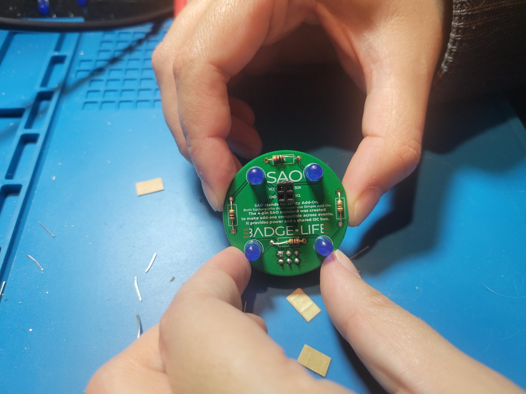
- Level 1 SAO
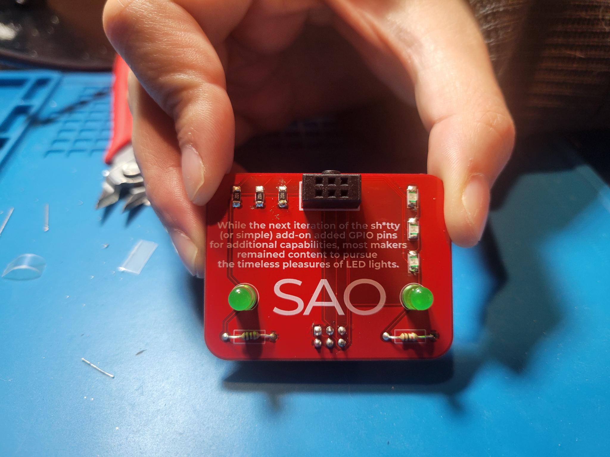
- Level 2 SAO
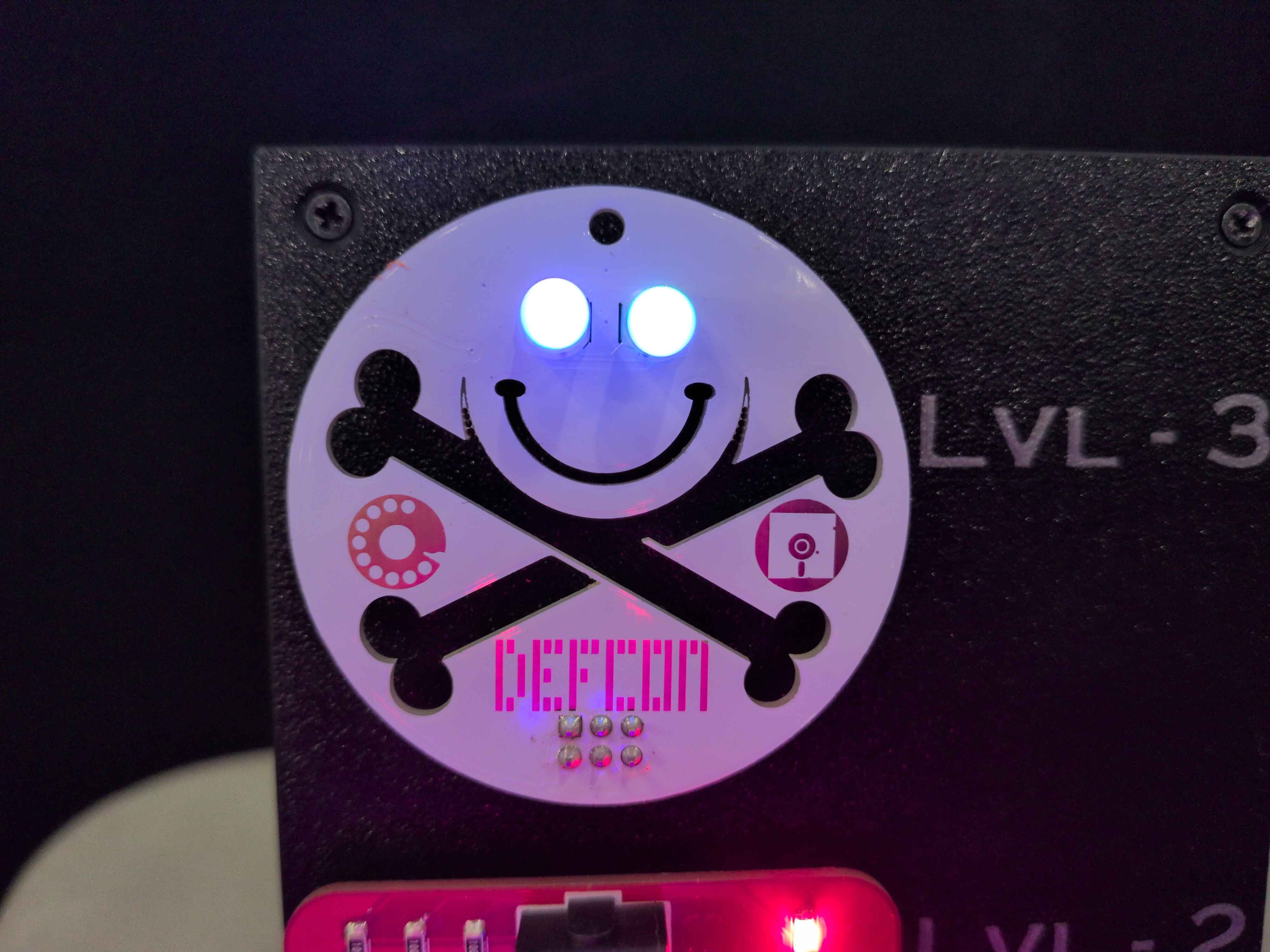
- Level 3 SAO
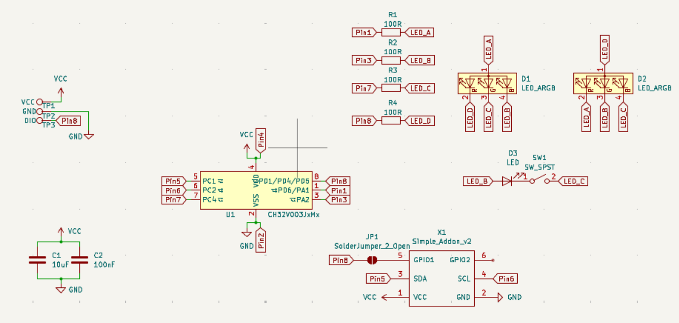
 Download Schematic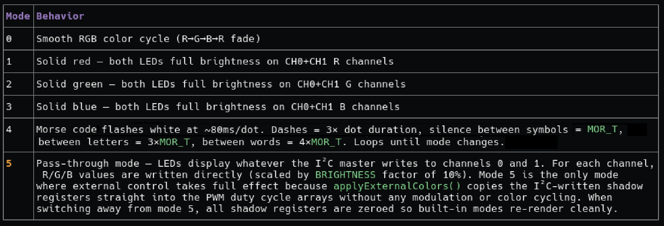
Soldering 101
I. The Basics & Vocabulary
- The process of making an electrical connection by melting low-temperature metal alloys around component leads
- Soldering is just as much an “Art” as it is a “Science”
- Pronounced “soddering” in American English – the “l” is silent!
- Circuit Board - the board part without components
- PCBA (Printed Circuit Board Assembly) - The circuit board along with all of its components
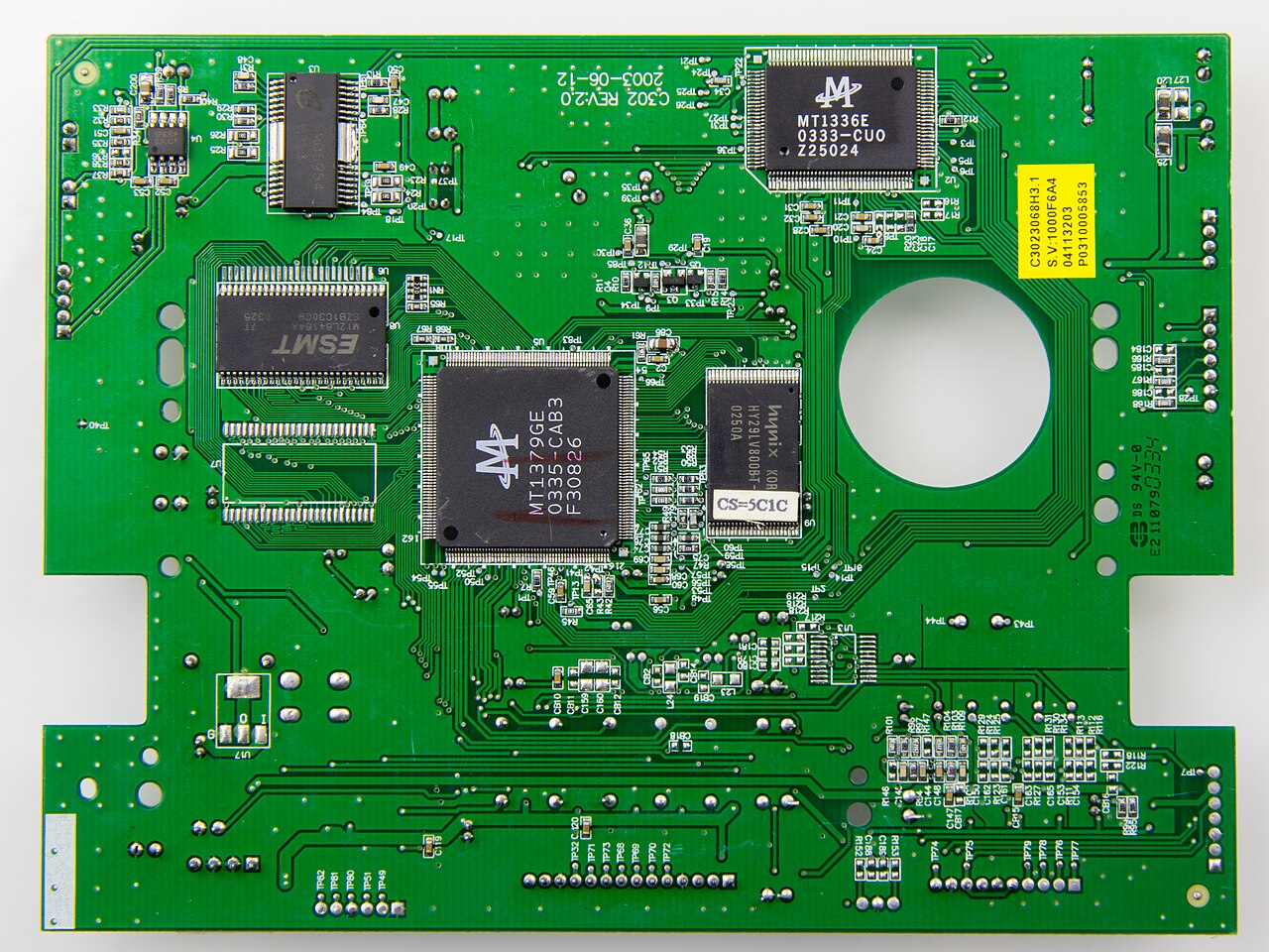
- Components - the parts on the board
- IC (Integrated Circuit) - Multiple components (like resistors, transistors, and capacitors) packaged together into a single unit
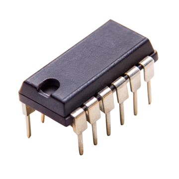
- Pins - each individual metal lead on a component
- Through hole component – has leads that physically pass through the board
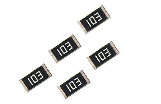
- Surface mount component – is flat and adheres to one side of a board
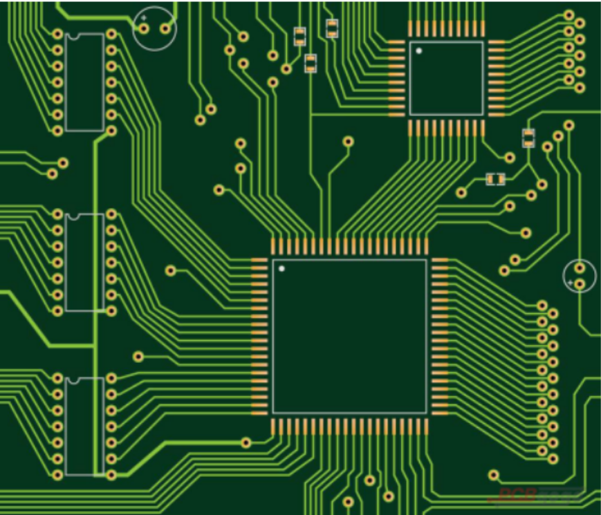
- Copper plate - the copper ground plane inside the board
- Trace – the underlying metal that connects components on a board (can be difficult to see – light green in this photo)
- Pad – the exposed metal that components adhere to (gold in this photo)
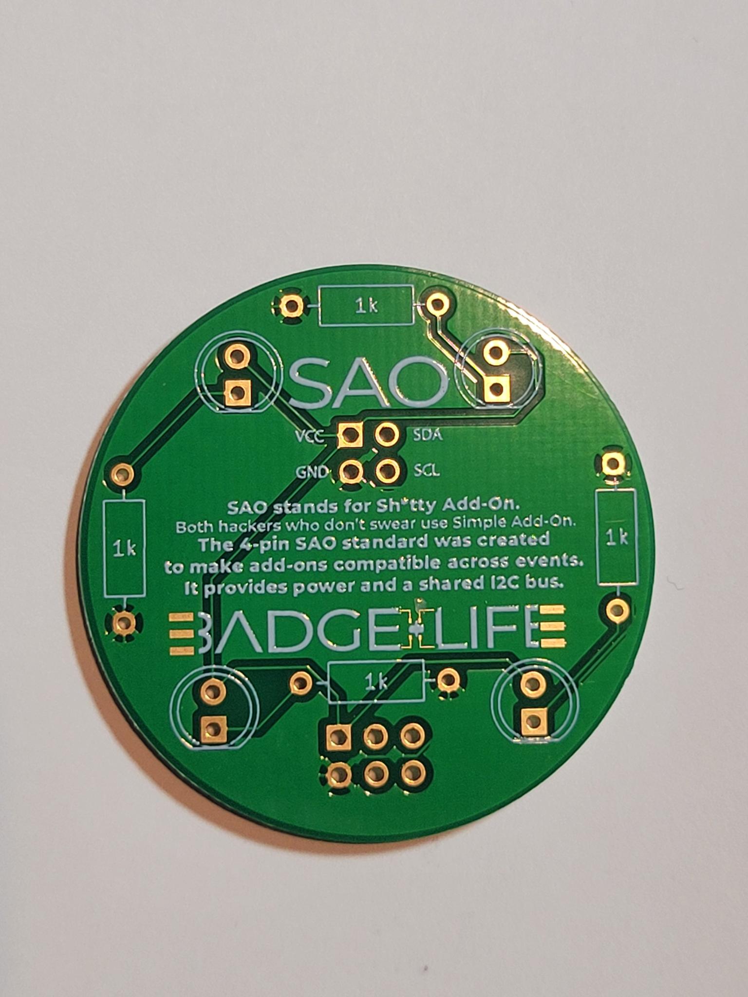
- Silk screen – the designs/writing on a board
- Solder Mask - a protective layer applied over printed circuit board copper traces to prevent short circuits, stop solder bridging, and block environmental corrosion. Also gives boards fun colors!
- Tinning – Putting a small amount of solder on the tip of the iron to protect it/prevent oxidation
- Soldering Iron

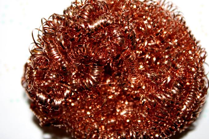
- Tip cleaning surface (sponge or brass)
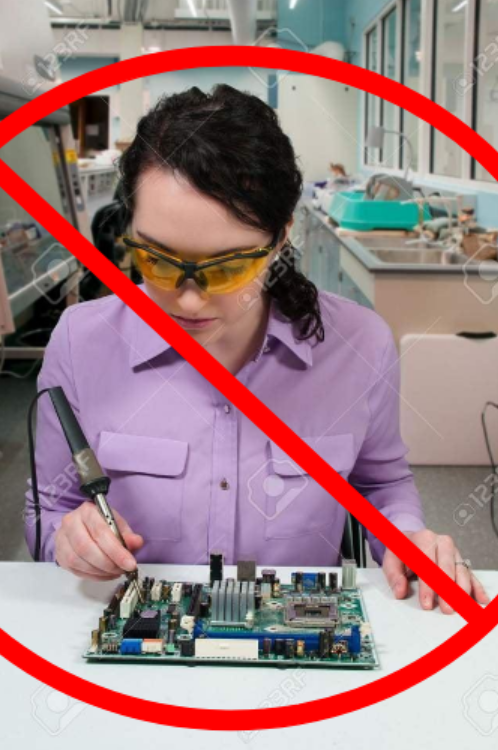
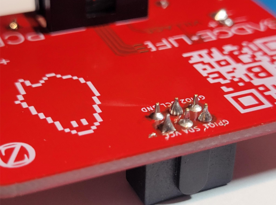
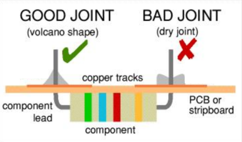
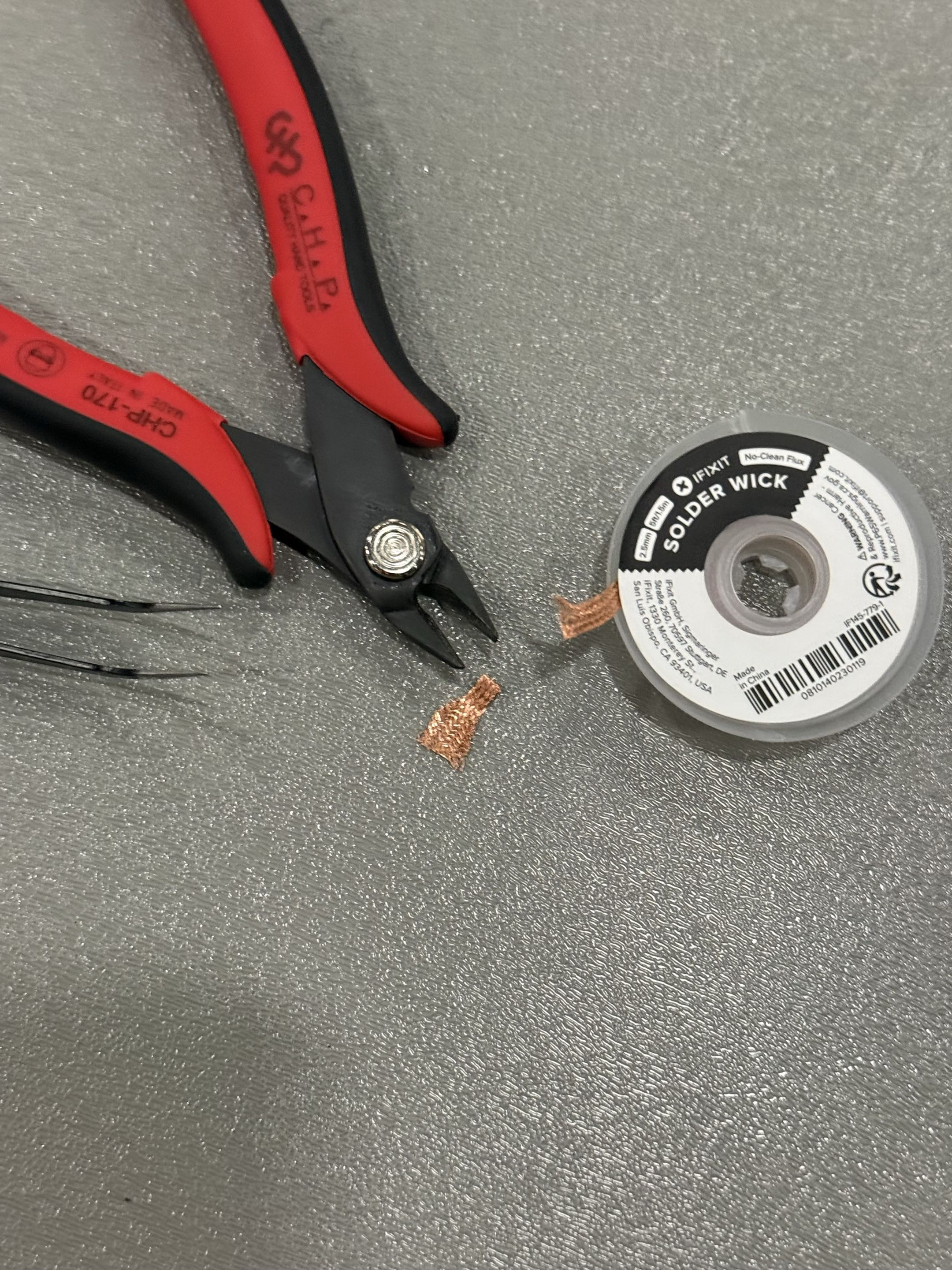
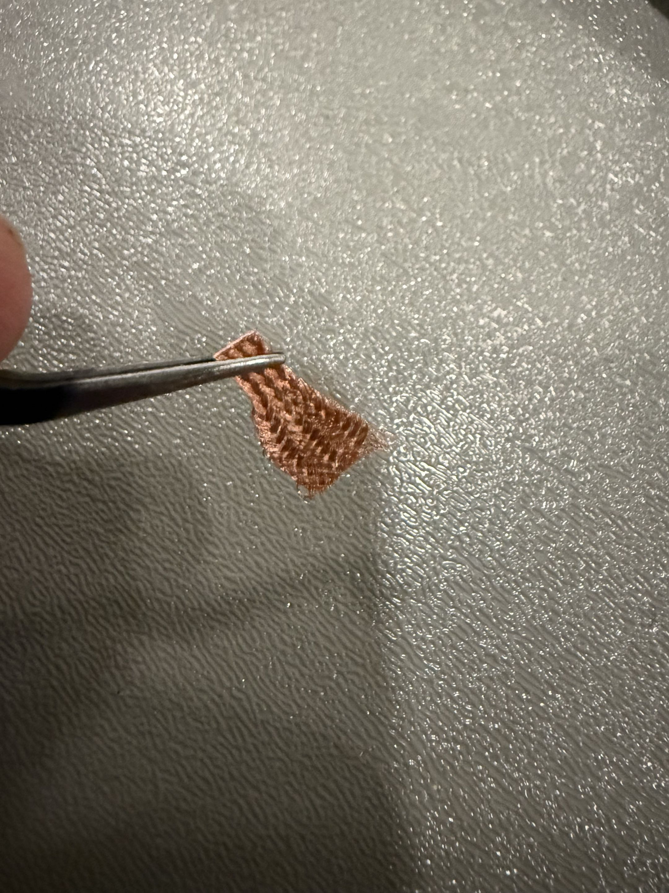
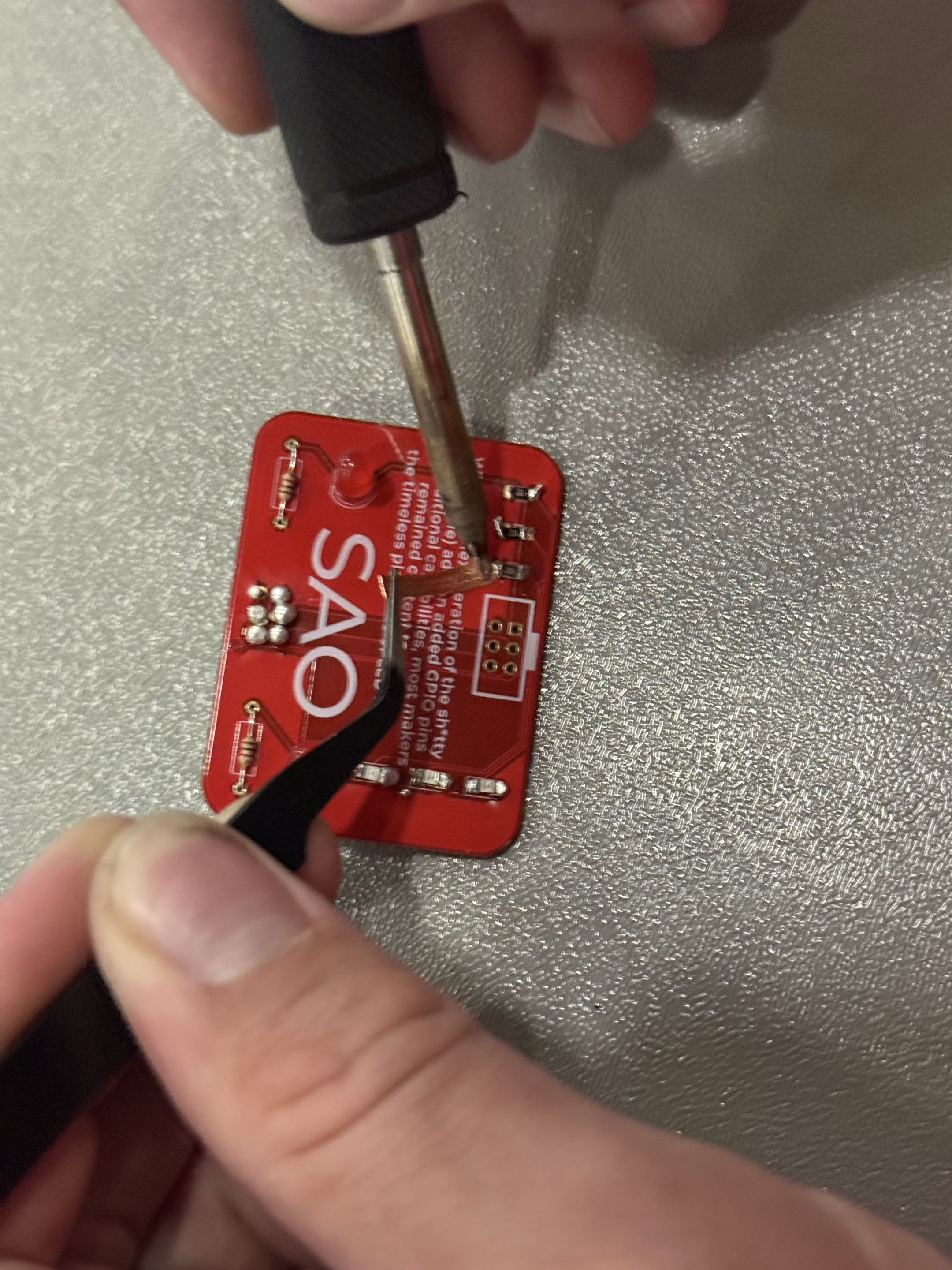
- Press the braid to the joint, then press your iron to the braid. The braid will absorb some of the solder
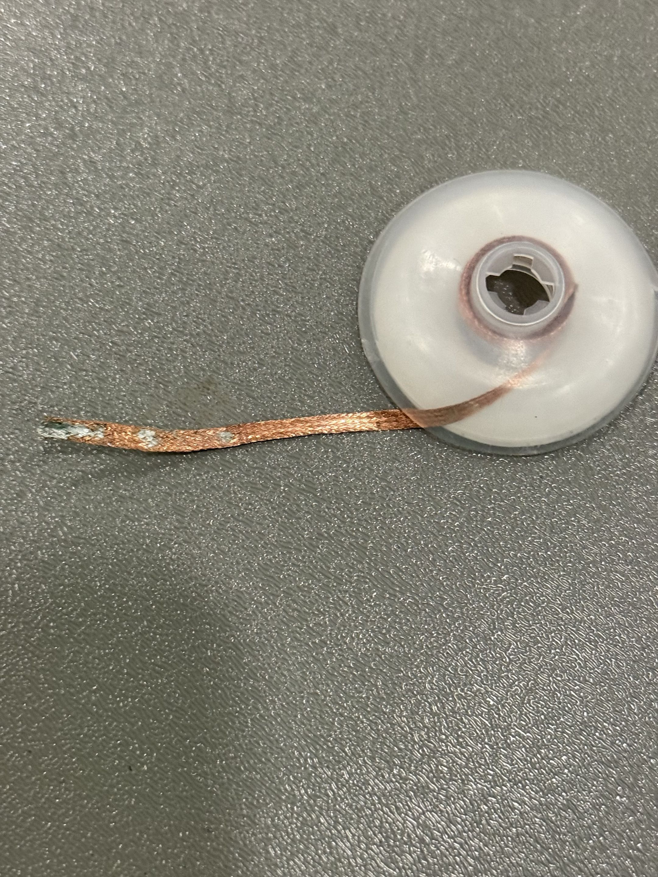
- Don’t be afraid to ask for help!
- BEFORE placing your component on the board, heat one of the pads and add solder
- Get ready to use your tweezers!
- While heating that pad with your iron on one hand, pick up your component with tweezers with your other hand
- Slide your component horizontally onto the heated/soldered pad
- While holding the component in place, remove the iron
- Wait for the solder to cool, then remove your tweezers
- Heat the other pad of the component and add solder, let cool
- All components should be in the bags
- Get your LEDs from the front table
- The silkscreen (writing) on the board will show you which way the components go, but you can ask a volunteer if you’re not sure!
- THE SIDE OF THE BOARD THE COMPONENT IS ON DOES MATTER. PUT THE COMPONENTS ON THE SAME SIDE AS DISPLAYED IN THE PHOTOS
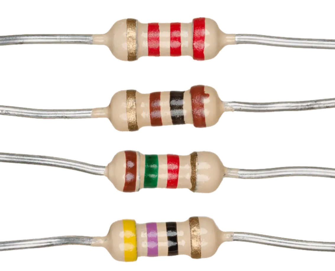
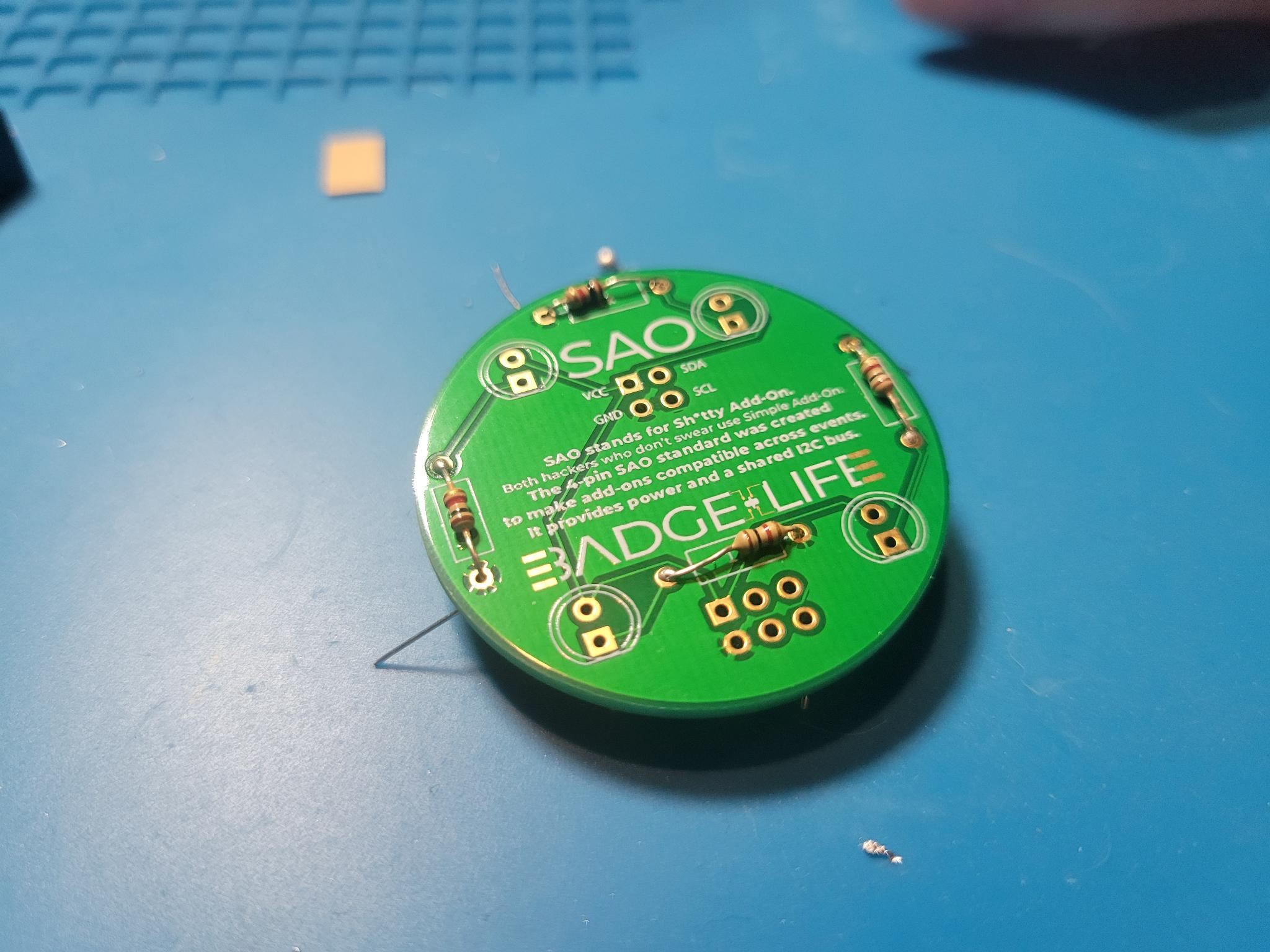
- Resistors:
- Resistors don't have an orientation! Put them any which way you like
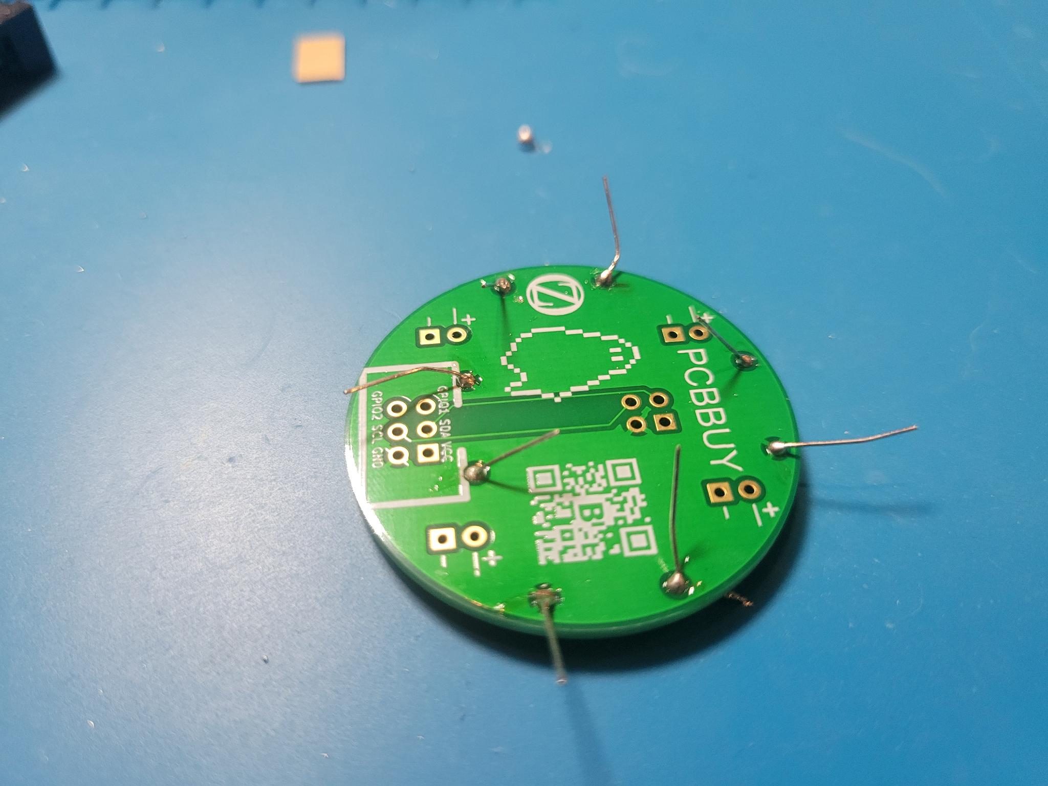
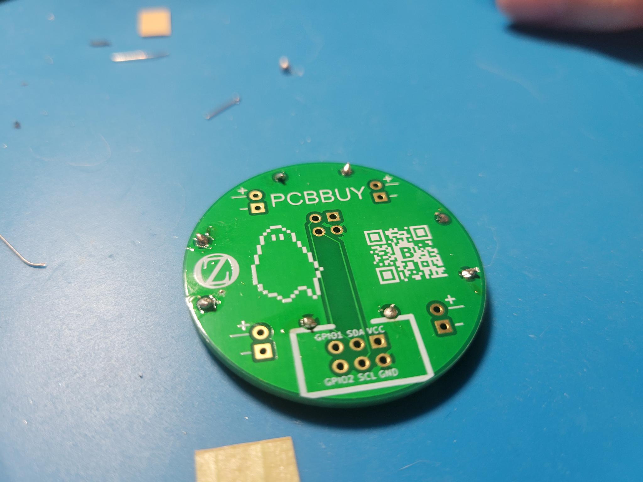
- LEDs:
- LEDS HAVE AN ORIENTATION! There is a right way and a wrong way. The long end is positive
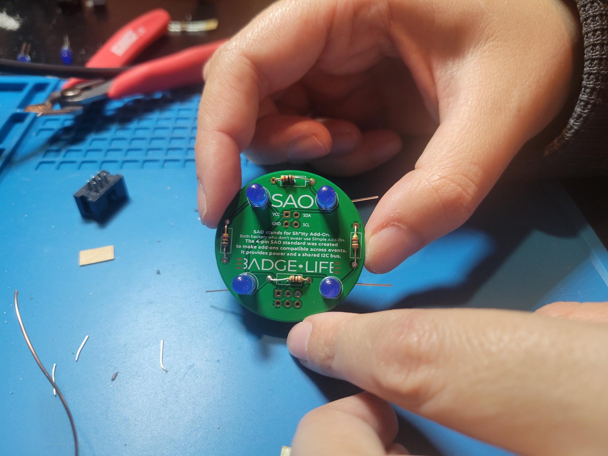
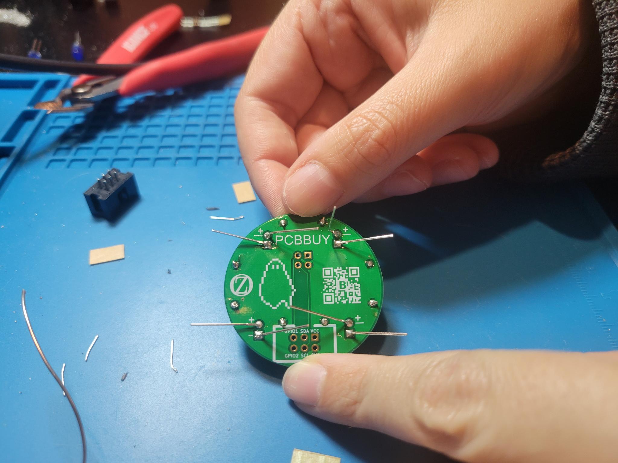
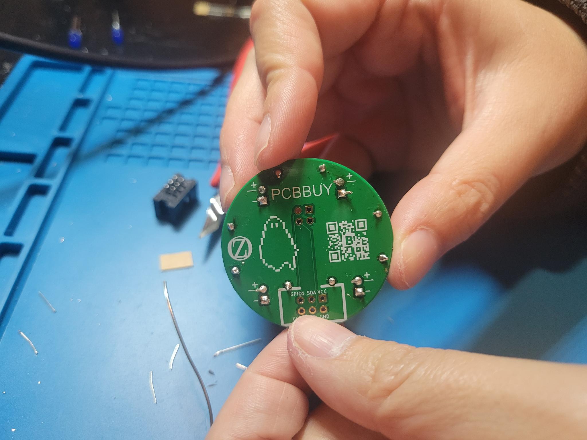
- SAO v2.0 Connector:
- This connector has an orientation! The gap in the housing matches the gap on the silkscreen
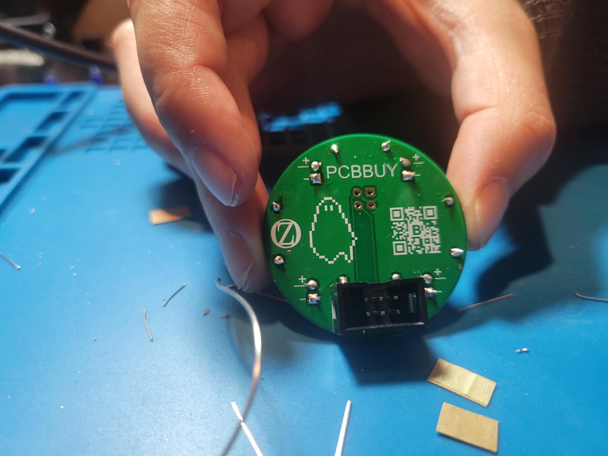
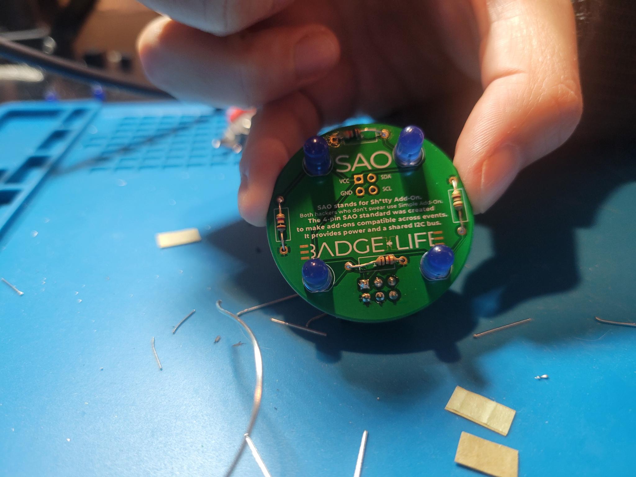
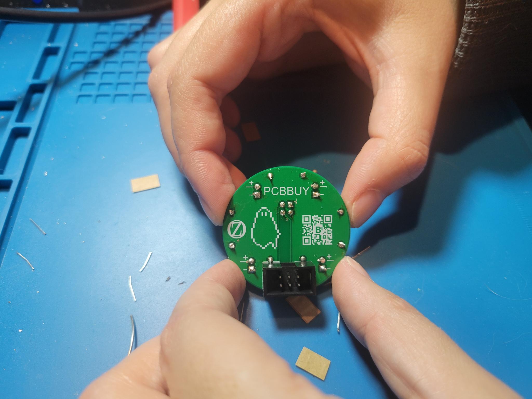
- SAO v1.0 Connector:
- This connector doesn't have an orientation! Put it any which way you like
- Through-Hole Resistors:
- Through-Hole LEDs:
- Remember that LEDs have an orientation!
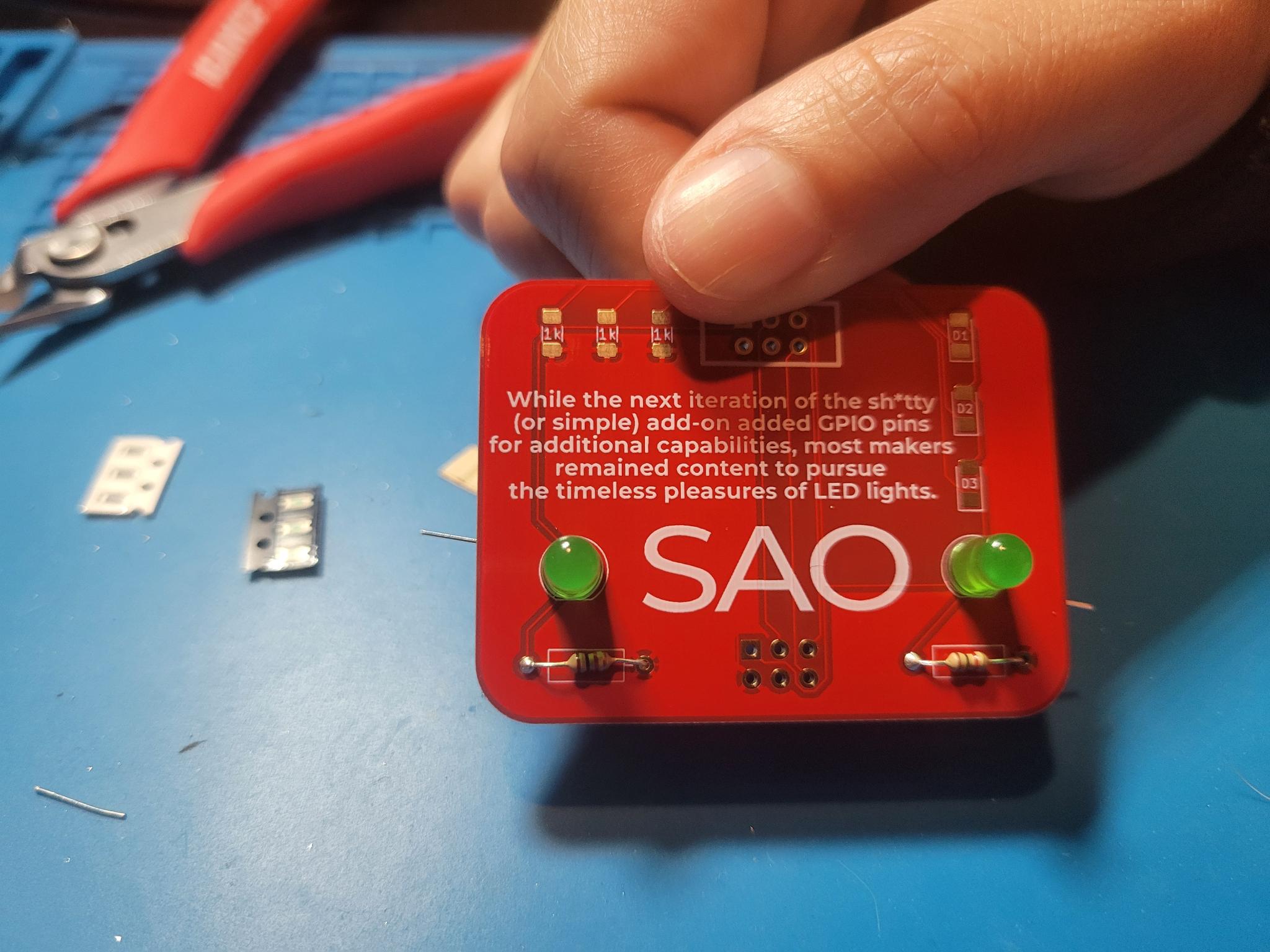
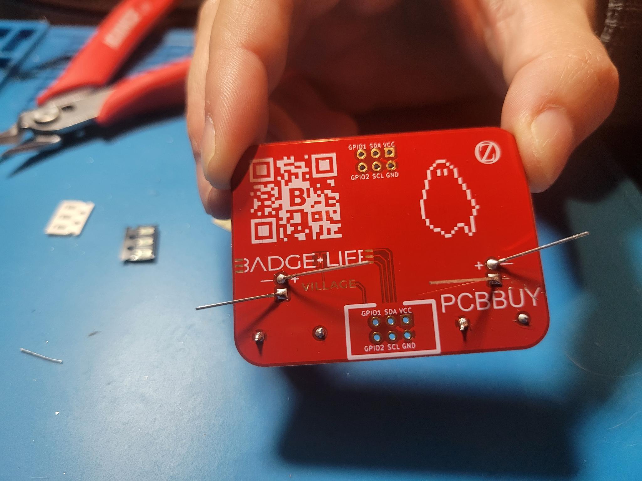
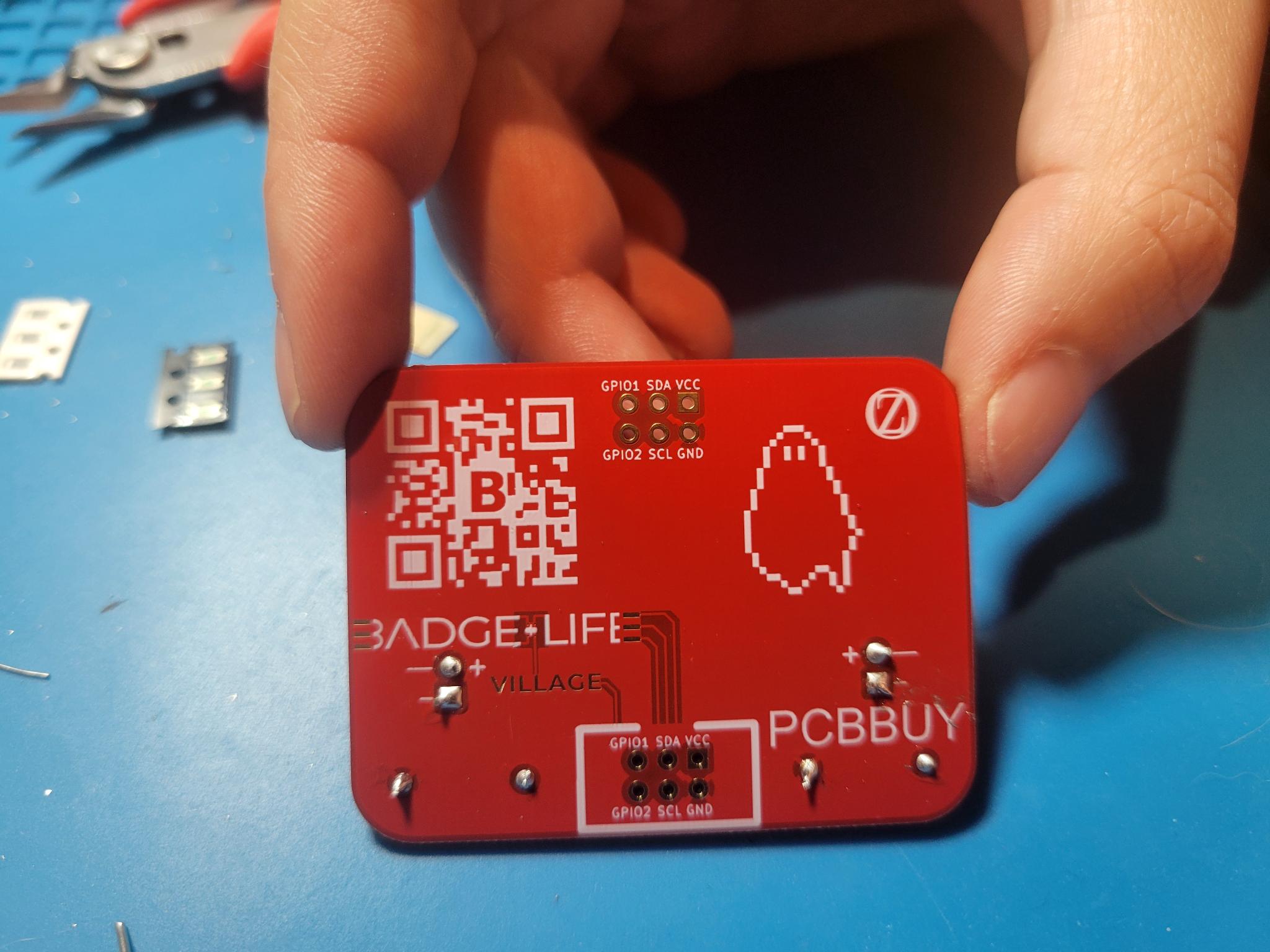
- Surface Mount Resistors:
- Surface mount resistors also don’t have an orientation! Still put them any which way you like
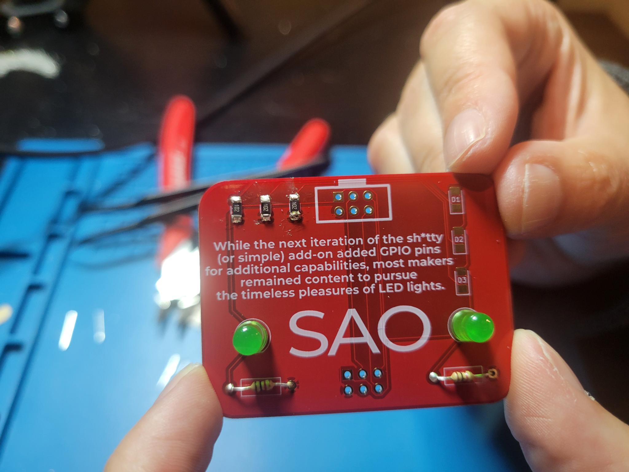
- Surface Mount LEDs:
- Surface mount LEDs also have an orientation! The arrow on the LEDs points down/to the bottom of the U-shaped silkscreen
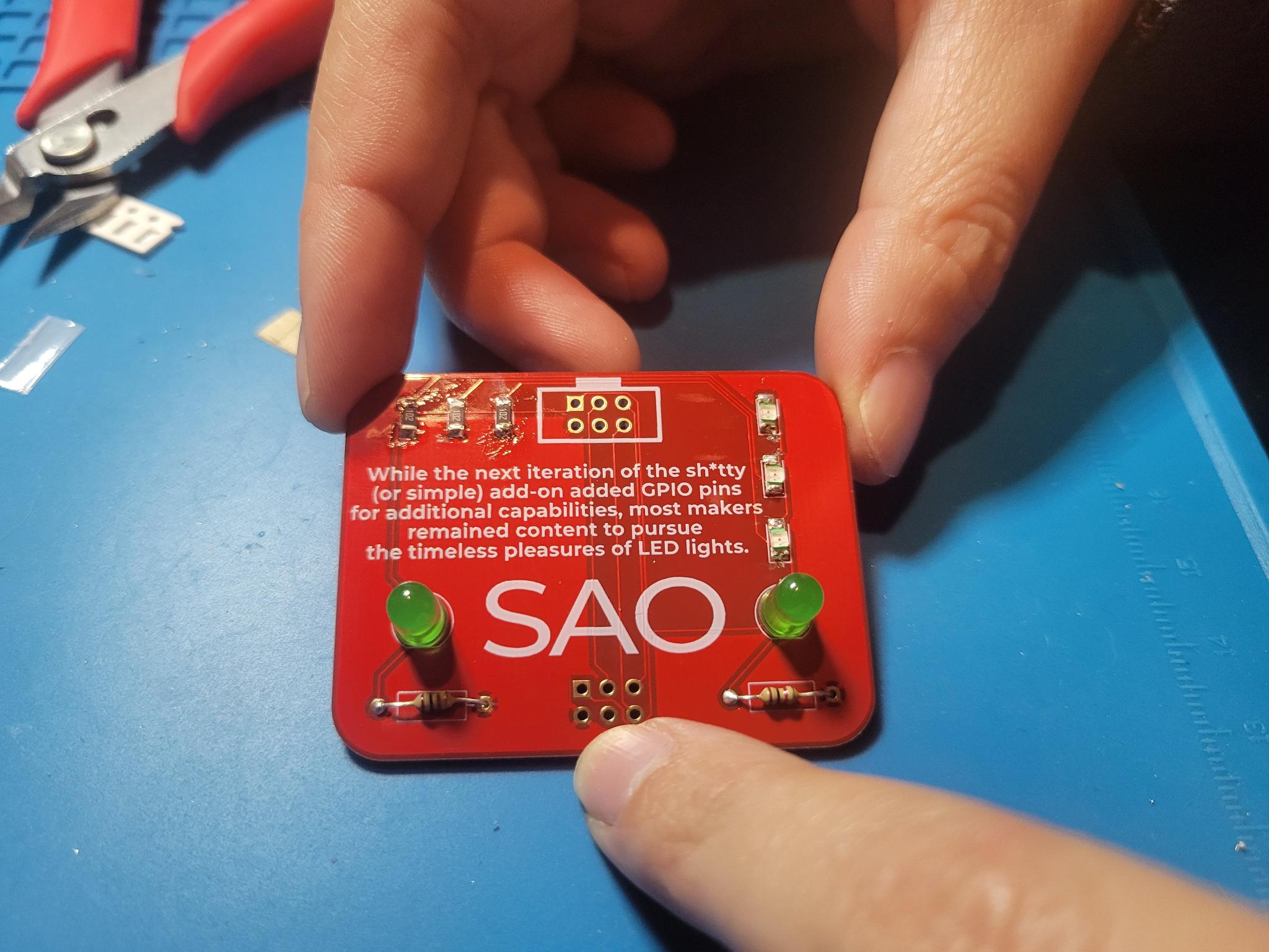
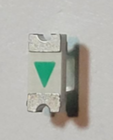
- Female SAO v2.0 Connector:
- This connector has an orientation! The key in the housing matches the bump-out on the silkscreen
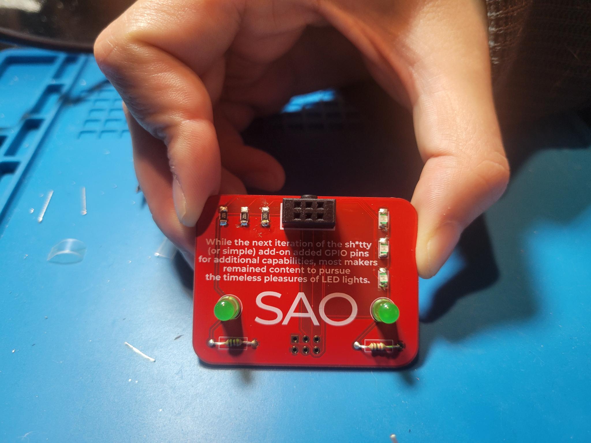
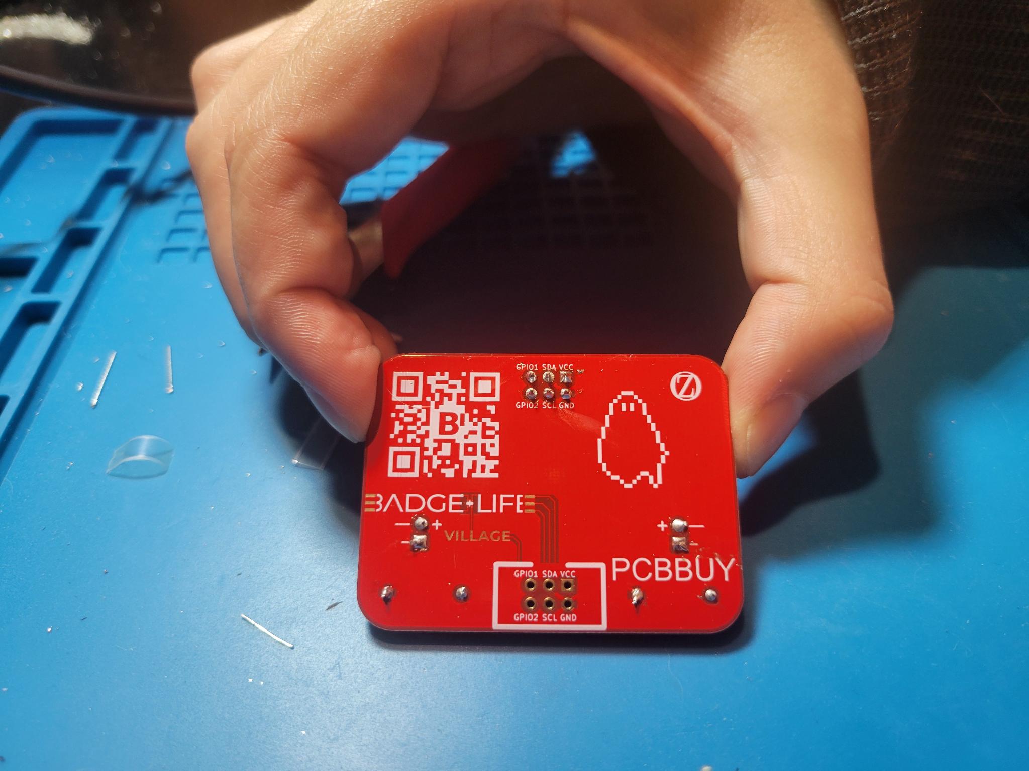
- Male SAO v2.0 Connector:
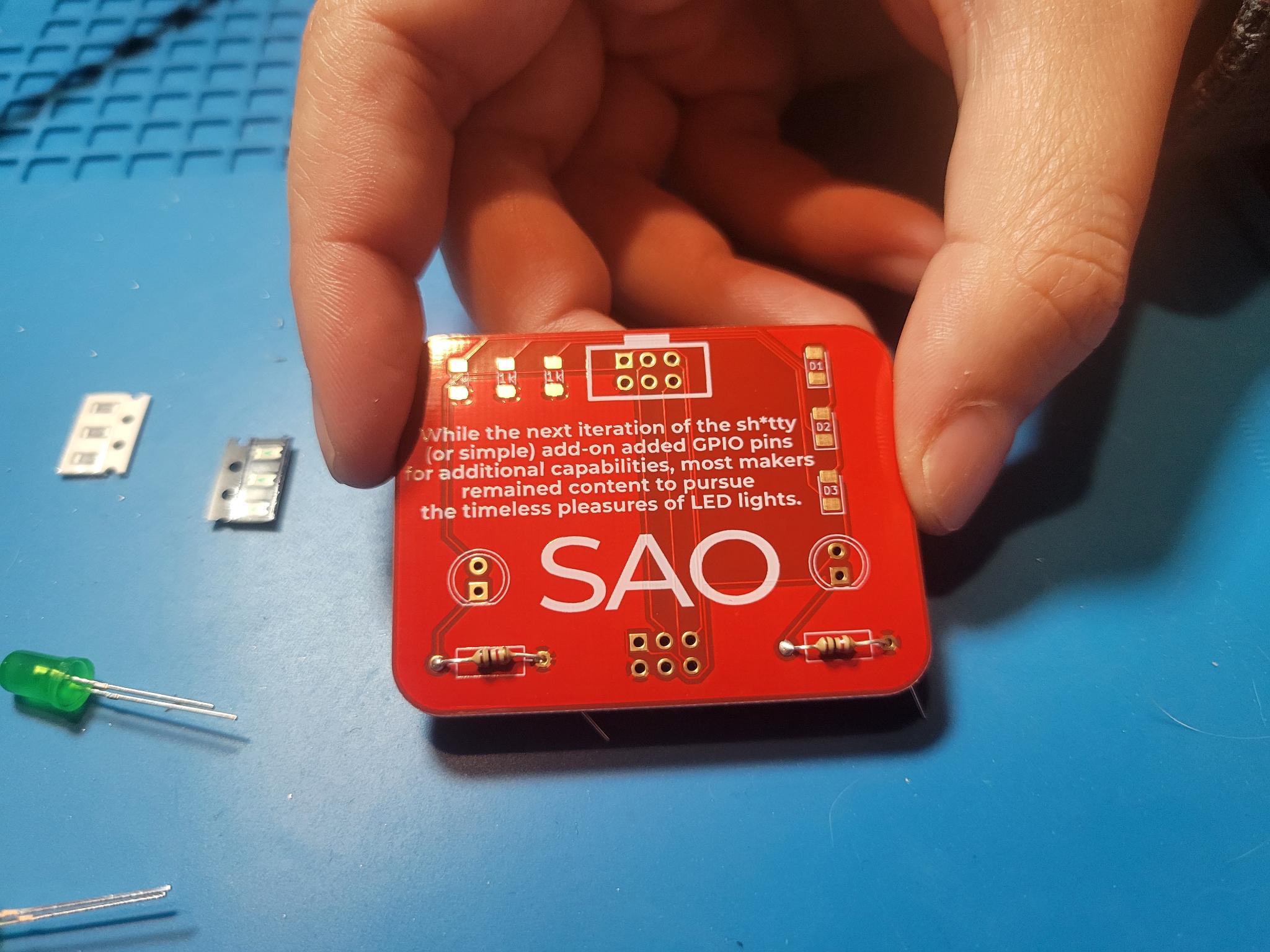
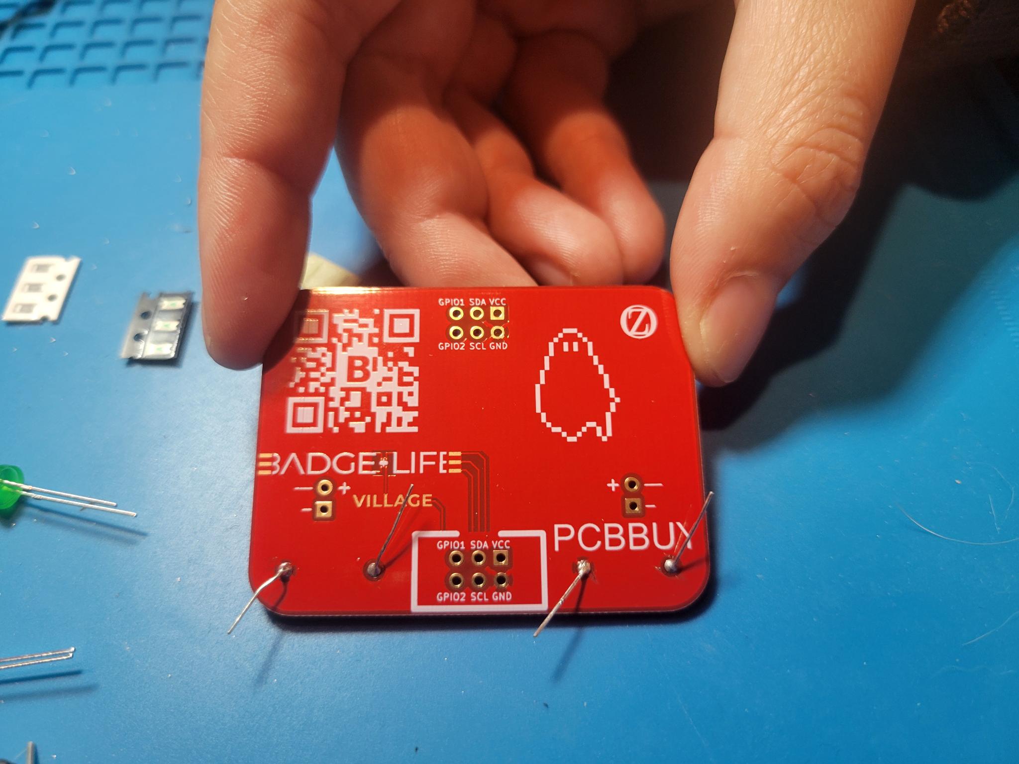
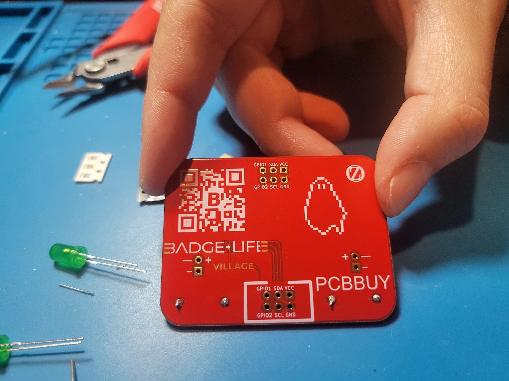
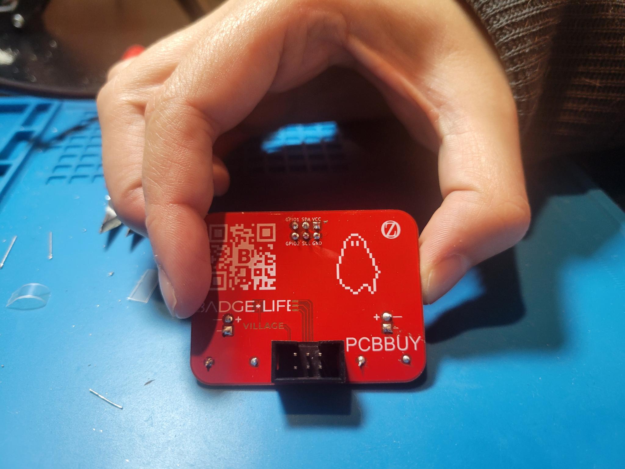
- This one is a challenge :)
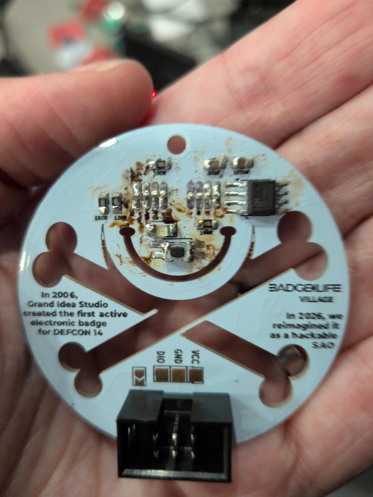
</ul>